Get a Grip on Print Quality
As use of 3D printing expands, designers are challenged to ensure quality control. New tools are emerging to help.

This wasn’t a large print, but it’s an example of a design that needed to be printed in parts, then assembled. The gripper body (nylon carbon fiber) and the claw (metal) parts are 3D printed in two different materials. Image courtesy of MakerBot.
Latest News
May 2, 2022
Consistency and scalability take center stage as additive manufacturing (AM) increases its mass production use cases. Is anything lost when a design is fabricated with a 3D printer? Can the same 3D design file printed in different places produce the same surface finish, rigidity or flexibility?
These are concerning questions as quality becomes a centerpiece in 3D printing. The technology is great. However, innovation must be monitored and examined to ensure it’s growing in parallel to hardware, software, materials and the quality control that supports AM.
Managing Delicate Designs
3D printing enables fabrication of many forms: from the finest lattice surfaces at a micro scale, to large industrial structures, the technology allows design firms to produce forms used to create bone structures, fine biological implants, affordable housing and emergency shelters. There are numerous considerations designers must consider when planning for such fabrication.
Zach Murphree is the VP of global sales and business development at Velo3D. He posits that conventional AM offerings and consistency between different machines has been a huge problem.
“Even when starting with an identical print file—the instruction file that the machine executes—the results on different machines will vary,” Murphree says. “Much of this is because each machine can have a different calibration and setup, and the process parameters for one machine will not produce the same results on a different machine, even if the two machines are the same make and model.
“If you wanted to expand your manufacturing capacity to another machine to meet demand, you had to create a print file with the machine-specific process parameters, build and validate the resulting parts,” he adds.
In addition to equipment considerations, it’s also important to be sure that the end product meets specifications.
“To take full advantage of the possibilities that 3D printing can offer, the application still needs to fit the requirements. For example, finely textured lattice structures offering an increased surface might be ideal for heat sinks where those structures would nonetheless be exposed and requiring maintenance,” says David Nguyen, mechanical engineering lead at Hubs. “For a lightweight application such lattice structures might have significant advantages but if the collection of dust would impair the functionality or significantly increase the maintenance this would likely not be acceptable. In these cases, it might be the best option.”
Vishnu Anantha is hardware design lead for MakerBot. He emphasizes that for professional applications, where tolerances and fit are a consideration, controlling variables is very important.
“At the baseline, separate from printer-to-printer considerations, a 3D print needs to be reflective of the properties of the final production part—whether that is injection molded, machined or 3D printed,” Anantha says.

He adds that with industrial grade machinery there is a great emphasis on controlling environmental factors.
“Features including sealed material bays and an enclosed heated chamber maintain a consistent quality of prints regardless of location,” Anantha adds. “However, there is always an element of variability that should be considered with in-house prototyping. When using a service bureau, you have greater control of the specifications you want.”
Christopher Robinson is a senior product manager at Ansys. He says that as 3D printing advances, Ansys has learned from their experience. Others should do the same.
“AM is really still making its way into the mainstream market,” he says. “We need designers and product development teams to question not only can we do it but should we do it?
“We have seen plenty of scenarios where AM has been used in either micro-scale or extremely large scale, where it is extremely beneficial,” Robinson continues. “But there are also situations where the only benefit is from a capability demonstration perspective.”
AM technology can complement other manufacturing technologies. For 30-plus years, according to Robinson, AM has generally been used within the scale of millimeter to meter.
“As we expand to adopt the research projects at smaller and larger scales, we need to be aware of the pitfalls not to fall into,” he says.
Diving Deeper into Quality
Robinson outlines numerous considerations when printing more delicate and finite designs. He says that although AM can facilitate the fabrication of complex geometries, it is not always the best idea to create such geometries as a single component.
“Cost is reduced significantly when a part can be built as a single unit rather than using traditional manufacturing to produce 20 or so components and joining them some way in an assembly,” he says. “However, that can certainly be problematic as well, because you can create a scenario where post-processing of the fabricated part is nearly impossible. I have seen many times where depowdering has not been considered in design and hours can be spent on trying to get powder released from parts.”
Robinson says every designer must consider any internal cavities during the design process. When using deposition techniques such as fused filament fabrication (FFF) or other methods, it can create internal channels.
But, the question, according to Robinson, is: Can you build those channels without a support structure?
“If support is needed, can it remain in the end part? If not, then how will you remove the supports? If you get the supports removed or if no supports were required, do you have access to these internal areas to make sure that surfaces are sufficient for the intended use and structural stability/fatigue life of the parts? One benefit of having the advancements of modern computation capabilities is the fact that a user can utilize process simulation to help in determining the amount of support structure that is needed in certain areas to guide the designer in alleviating these concerns and making decisions early in the process,” he explains.
Each manufacturing technology has constraints, according to David Pierick, 3D printing application development manager at HP.
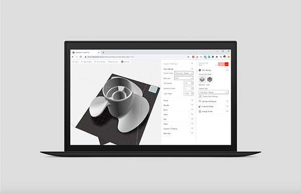
The image shows a sliced view of a propeller on MakerBot CloudPrint, which could show the CAD file after it’s been uploaded to a slicer program and ready to print. Image courtesy of MakerBot.
“Injection molding requires draft angles, making the part design much closer to that of 2D than 3D designs. There also must be draft angles on any vertical surface for injection molding, or a part cannot be removed.
There also can’t be blind surfaces that can limit design freedom, according to Pierick. “For additive manufacturing, constraints often depend on the type of technology used. For example, considerations must be taken with powder-based lattice structures for powder removal. Resin-based technologies must consider support structure removal.
Hardware, Software and Format Architecture
Another concern regarding transferrable designs is software and hardware architectures and formats. Is the industry moving from stereolithography (STL) CAD format to the more modern 3D manufacturing format (3MF) format as a means of expediting printing? Does file format matter when printing is dispersed among different vendors and suppliers? Is this a problem?
David Giebenhain is the 3D printing global product director at Protolabs. He says the STL file format is far from perfect and that the only data these files capture is a mesh representation of a geometry. He says the accuracy of that mesh varies widely, and the physical file sizes can be immense.
“There is a desire among designers and manufacturers to move to a file format or process that better captures design intent and critical manufacturing parameters—things like unit of measure, color, material, texture and print parameters among others. The 3MF file format does convey more of this information, which may reduce some variability between two different suppliers, but it cannot nor is it ever likely to replace quality standards and quality management systems,” says Giebenhain.
Calibration Challenge?
One important consideration of file transferability when it comes to scale and designs is how enterprises ensure hardware is calibrated with the same settings to produce the same results regardless of time or place of the print job.
“The challenge in conventional additive manufacturing systems has been that complete calibrations are time-consuming and therefore costly to do on a frequent basis,” says Velo3D’s Murphree. “I think that the onus is on the machine manufacturers and solution providers to make calibrations straightforward and fast. These solutions need to be built in, and they can’t require that the user be a Ph.D. in optics in order to perform them successfully.”
Modern solutions, like Velo3D’s Sapphire portfolio, have one-click calibration that, according to Murphree, can be performed with minimal effort and no external metrology equipment.
“This sort of solution will become the industry standard if we are to get to the consistency levels required for much broader adoption of AM,” he says.
Nihal Velpanur, product manager at PTC, adds that having a standardized process of certification for each machine is important.
“Introducing a real-time monitoring process for the key process indicators, both within the machine and part of the overall manufacturing processes, along with the capability to make real-time adjustments or compensations as part of a robust closed-loop monitoring system will go a long way in ensuring enterprises have successful production runs with their 3D printing hardware,” Velpanur notes.
Towards an Efficient Overall Process
In short, designers must focus on a more efficient overall process, from beginning to end, when designing and fabricating via AM.
Best practices in designing for 3D printing are constantly evolving, especially with advancing 3D printing capabilities for large-scale components, according to Danielle Cote, an assistant professor of mechanical and materials engineering at Worcester Polytechnic Institute in Worcester, MA.
“As part size and deposition rates increase, the process resolution tends to decrease. This leads to larger near-net shaped parts, which tend to require post-process machining or finishing operations to achieve a desired final geometry and surface finish. Designing parts with this post-processing requirement in mind can create a more efficient overall process,” Cote says.
More Ansys Coverage
More Hewlett Packard Coverage
More MakerBot Coverage
More Protolabs Coverage
Subscribe to our FREE magazine, FREE email newsletters or both!
Latest News
About the Author
Jim Romeo is a freelance writer based in Chesapeake, VA. Send e-mail about this article to DE-Editors@digitaleng.news.
Follow DE