New Software Tool Takes Guesswork out of Metal AM Part Orientation, Supports


Latest News
April 9, 2018
Could letting go of your preconceived ideas about defining the best AM support structures solve thermal distortion problems?”
Sunata software, designed to work seamlessly with direct metal laser sintering (DMLS) printers, automatically chooses the best part-orientation and generates the optimal support structure. As anyone who starts working with metal AM part design and production immediately learns, this support structure not only attaches the various angles of a part to the build platform but also provides a critical path for heat transfer, minimizing internal stresses and subsequent part deformation.
Ending Trial-and-Error Guesswork
As much progress as there’s been in many aspects of metal AM over the past few decades, a nagging, time-consuming task has been deciding how best to orient a part in the build volume. Every possible XYZ orientation requires a unique support-structure geometry, so this decision has a large ripple effect, from build time to thermal response to material use. At the same time, sub-optimal orientation can cause recoater-blade crashes (as the wiper smooths a new layer of powder over the partially printed shape), part delamination (pulling away from the build plate) and other problems.
Several software companies now offer finite element analysis (FEA)-based stress simulations of 3D CAD models destined for metal AM production. These tools require users to choose a part-orientation, run the simulation, evaluate the results, choose another orientation, and try again. Such a trial-and-error approach can be quite time-consuming, and there’s no way to confirm that the final choice is the optimal one.
Sunata software is fundamentally different and replaces these simulation products. Funded with $1.6M from America Makes, Sunata is the result of a project begun in 2014 by Indiana Technology and Manufacturing Company (ITAMCO) in collaboration with the University of Notre Dame, the University of Pittsburgh and Johnson and Johnson Depuy Synthes. After perfecting the new software tool with more than 3,000 simulations and nearly 100 physical print confirmations, ITAMCO launched Sunata in April 2017 as a commercial product under the spin-off company Atlas 3D. Delivered as a secure, cloud-based software, Sunata is already in use at service bureaus, government laboratories, universities, AM system manufacturers and Fortune 100 companies.
New Math Speeds up Simulations
Based on a new, patent-pending thermal circuit network (TCN) approach, Sunata software automatically parses a 3D CAD model into thermally similar layers that are then sub-divided into thermally similar segments. The software runs through 100 possible part orientations and support structures to identify the optimal configuration. Users can scale their requirements from next-to-zero distortion with longer print-times to more tolerable distortion with shorter print times, gaining accurate cost-to-print data, according to the company.
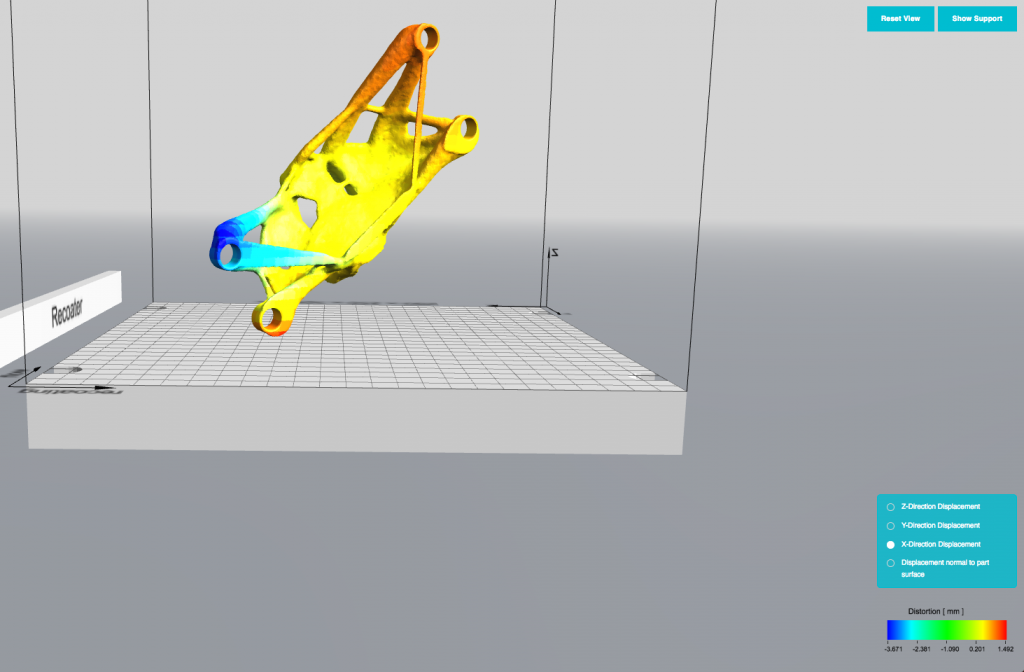 Expected distortion along the X-direction, for an additively manufactured metal part, oriented so that the necessary support structure involves minimal removal effort. Displacement in Y, Z and normal directions can also be viewed. All calculations performed with Sunata, the cloud-based Thermal Circuit Network (TCN) solution from Atlas 3D. Image courtesy Atlas 3D.
“Instead of using traditional elements to discretize the part and compute the temperature, we slice the part into layers and model each layer with a network of thermal capacitance and resistance,” explains Hao Peng, vice president of product development at Atlas 3D. An analogy to this approach is an electrical network of capacitors and resistors. Peng says the TCN solution was chosen because it can generate results faster than with FEA, with comparable accuracy.
Part of Sunata’s high-speed response time is due to its hosting on the cloud through Amazon Web Services (AWS). This means users can even access the software on a cell phone. The tool is also available on the AWS Government cloud for anyone operating under International Traffic in Arms (ITAR) compliance regulations.
Step-by-Step Ease of Use
Users begin a session by purchasing or redeeming credits, uploading an STL model file, selecting the part material, and selecting their AM printer. Current materials include aluminum, SS 316L, SS 174 and Ti6Al4; current systems include the M290, M100 and M400 models from EOS and the 280 from SLM, with the Renishaw M400 about to be added. The interactive web session then guides users through verifying about a dozen process parameters, almost all of which are pre-populated according to the selected AM system.
Beyond entering an optional scaling factor for model build-size and choosing the units (typically millimeters or centimeters), users are actually encouraged to accept the system-specific default values for the following process parameters: laser scanning speed, laser beam diameter, laser power, element size, powder layer thickness, critical support angle, and distance between the part and the build plate (nominally zero).
Chad Barden, Atlas 3D CEO, notes that his company is trying to provide an “Easy” button for this critical task, and that goal causes them to walk a fine line. Users are accustomed to simulation and design tools having lots of levers to pull (i.e., parameters to manually change), he adds, but that immediately backs off on the full power of a computational approach.
“Rather than going along with a designer’s 'black-art decisions' about where supports should or should not be,” says Barden, “users need to have some faith. We are saying, look – this is the answer, this is the optimal orientation for the parameters that you put in, and you need to believe in it.”
Output graphics show the part either as it would appear post-support removal, or with supports attached along with potential stresses. If not acceptable, users can then decide to redesign the part to get a better build. Sunata is predicting thermally warped displacements within 10% of actual displacements as measured on test parts with CMMs.
Plans include adding more AM systems and materials, and providing answers in near real-time. Barden says they are working with a national laboratory to improve the performance of the TCN method and feel they will achieve a 100x speed improvement.
Users can work with the tool on a pay-as-you-go basis, running one job per credit purchased; however, Atlas 3D also offers monthly, annual and multi-year subscriptions as desired. A final bonus: the guarantee. If a user does not get a successful build (defined as the part printing within spec, with no delamination or recoater-blade crash), the company grants a credit toward an additional run.”
Subscribe to our FREE magazine, FREE email newsletters or both!
Latest News
About the Author
Pamela Waterman worked as Digital Engineering’s contributing editor for two decades. Contact her via .(JavaScript must be enabled to view this email address).
Follow DE