3D scanning software such as Artec ScanApp leverages advanced data capturing and processing algorithms, with an eye toward developing highly accurate 3D models. Image courtesy of Artec 3D.
Latest News
September 1, 2021
Gone are the days when reverse engineering lurked in the shadows of military and commercial espionage. This engineering practice must no longer be a laborious, time-consuming process that requires engineers using calipers and rulers to measure every square millimeter of a product’s surface geometry.
Reverse engineering is in the midst of a radical metamorphosis. Fundamental building blocks like intent, use and technologies are moving beyond the pale of traditional concepts and toolsets.
But why now? What was the catalyst for this tectonic shift? How will it affect design engineers and manufacturers?
To answer these questions, you must recognize that the momentum driving the “new reverse engineering” springs—at least in part—from an industrial context shaped by trends such as the rise of additive manufacturing (AM) increased customization, production decentralization and manufacturing on demand.
All these factors have diminished the footprint of traditional concepts like economy of scale and mass production and replaced them with business models and engineering practices that promote shorter development cycles and greater market agility.
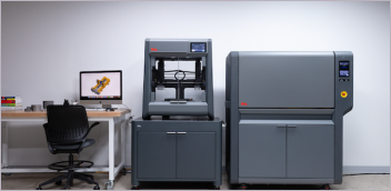
As for the catalyst of change, look to the dynamics created by advances in 3D scanning and scan-to-CAD technologies, as well as to the increased access to greatly enhanced computing resources (Fig. 1). These developments have recast reverse engineering in new, high-profile roles that promise to take digitization to new levels in the industrial sector, which transforms the way firms design and manufacture products and components.
Leaving Manual Data Capture Behind
Look at reverse engineering at its most basic level, and you realize that its metamorphosis began with the shift from manual data capture to digital data acquisition.
Traditionally, reverse engineering required designers to perform a large number of physical measurements, sketches and annotations to accurately translate data from the physical world to the digital domain. Designers needed to proceed one step at a time, with iterations between measuring and designing, a process that repeated itself multiple times, depending on the complexity of the project.
The very nature of this process limited the situations in which you could cost-effectively apply reverse engineering. Even in these cases, the lack of precision and accuracy greatly diminished the rewards derived from the process use. All this made reverse engineering a prime candidate for a technology revolution, a challenge that software providers have worked hard to deliver.
New Technology, Greater Efficiency
In 2021, 3D scanning systems provide engineers with highly precise data, which enable them to create complete 3D models for reverse engineering—either a point cloud or a mesh—significantly faster than traditional tools. These models can then be used as a mockup that designers can follow directly inside the CAD software.
“This allows for a much more accurate and accelerated reverse engineering process,” says John Chan, software product marketing manager at FARO. “Contours can be extracted from highly dense 3D scans for the design itself. Furthermore, there is much less approximation of complex structures and surfaces that in certain cases would be near impossible to measure manually. Features on the scan can literally fit a geometrical feature on the item scanned, with micron-level approximation, as well as use constructed geometries on the point cloud to constrain the features created to the most accurate measure possible.”
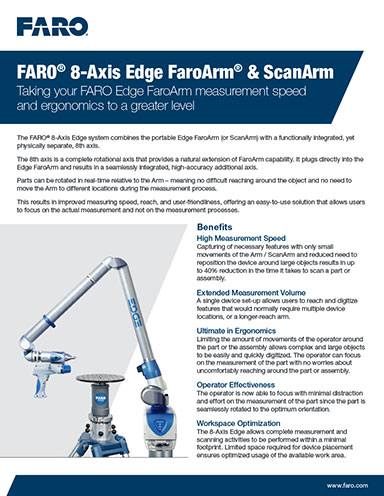
Essentially, with one sweep of the scanner, an engineer can now capture millions of data points across surfaces of all complexities, with submillimeter-level accuracy. The result is greater efficiency (Fig. 2).
“With 3D scanning, reverse engineering workflows are 300% to 500% faster, with repeatable precision,” says Andrei Vakulenko, chief business development officer at Artec 3D. “This empowers manufacturers with a greater degree of business agility via a much faster time to market, combined with reduced labor and material costs.”
Assembling the Building Blocks of Designs
To deliver these benefits, 3D scanners, with a variety of technologies, collect data that describe in detail the shape and appearance of the physical object in question. This includes defining its structure and environment.
This workflow typically begins with an assessment of the requirements, including accuracy, level of detail and scale.
“These combinations of variables can drive the hardware to be a sub-micron [computed topography] scanner all the way to a terrestrial LiDAR system capable of scanning literal landscapes of data,” says Greg Groth, division manager, Brookfield, WI, operations, at Exact Metrology.
In the scanning process, the system identifies 3D points, calculated from photos and depth measurements. Once combined, the data forms a point cloud.
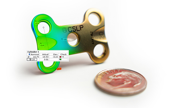
When the scanner creates the point cloud, it processes the data to create a polygonal mesh, which connects the dots of the point cloud to produce a complete 3D model. The mesh represents the surface of a shape with a collection of vertices and surfaces, and it includes information that describes how the vertices make up the surfaces. Mesh models don’t contain any information about the object other than the position of the triangles that define the shape (Fig. 3).
The extrapolation process of the object’s shape from points is known as reconstruction.
Bringing the Picture into Focus
Capturing measurements and defining shapes and surfaces, however, is only half the battle. As nice as it would be to have a 3D scanner that creates instant CAD models, no such technology exists. Most CAD offerings cannot work with the direct output of a 3D scanner.
The problem is that pure scanned data consists of extremely dense meshes that represent several million coordinate points or triangles. Basically, meshes are averaged point clouds interpolated into a triangle structure. This data is aggregated in mesh files, either in STL or OBJ file formats.
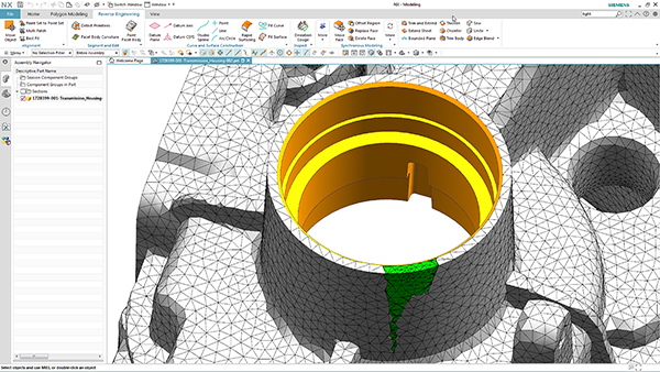
Before the data can be put into a ready-to-manufacture model, however, the engineer must align and optimize the mesh file (Fig. 4). This means extracting dimensional properties through geometrical entities, cross-sections and surface patches. Only then can these entities be exported to CAD software and used as reference data to create the final 3D model.
This is where scan-to-CAD toolsets come into play, but this phase of the process is not without its challenges.
Processing Challenges
For one, scanned data consists of thousands or even millions of small triangles. For a more accurate model, the engineer must measure more points. More points translate into a finer mesh, but they also mean that processing becomes more difficult.
A common approach is to convert the scan data into accurate math-based data. This requires scan-to-CAD workflows to eliminate redundancies and reduce the volume of data by culling relevant information from the larger digital representation provided by the 3D scanning.
This already difficult process is further complicated by the presence of noise.
“No matter how careful the scan is undertaken, there will always be noise—small fluctuations in data that will appear in the model that need cleaning up,” says Robert Haubrock, senior vice president of product engineering software at Siemens Digital Industry Software. “The important factor here is making it easy to identify and fix these small blemishes in the data. This means being able to quickly map cylinders, planes and edges into a model to make it easier to get a clean model.”
Ultimately, the scan-to-CAD workflow translates points or triangles into discrete features, surfaces and solids. The smoother and simpler the process, the more effective the toolset. Yet it can be difficult to find the right combination of tools.
“The main market challenge is getting the best tool for this translation into CAD,” says Chan. “We have software that answers part of the reverse engineering need as it allows a user to translate a certain model into a CAD-digestible format, but it does not allow bringing all the information into CAD. While it basically wraps the mesh into approximated surfaces that follow the curvature of the part itself, users still need to continue the reverse engineering workflow within the CAD software environment.”
The Human Factor
In its current state, 3D-scan-to-CAD technology lacks the automated processes found in more mature software platforms. The fact is that these workflows are not fully automated with the push of a button.
This means that, for now, engineers play a critical role in the process.
“Human intervention by a qualified specialist is still required to interpret the mesh data and enhance it to create the CAD 3D model,” says Simon Côté, product manager at Creaform. “As such, this process requires some skills and know-how to accomplish, and depending on the quality of the scan-to-CAD solution as well as the complexity of the project, can be anywhere from easy to challenging.”
![]()
A Starting Point for Reverse Engineering
Despite these challenges, the speed, agility and precision promised by 3D scanning technology is opening the door to a whole new class of reverse engineering use cases. To see what the technology can do, firms must keep in mind the basic intent of this long-standing engineering practice.
At its core, reverse engineering seeks to obtain information from, and even develop a design based on, a finished component or product. This means identifying the parts that make up the product, determining how they interact with each other, and defining how the product was manufactured.
The first step in this process is to take measurements of the existing part, using them as a guide for building a new CAD design file. This is where a 3D scanning system comes in handy, especially when reverse engineering a part with complex geometries that are difficult to measure any other way.
These scanners are proving to be well suited to make the measurements of the part in question, providing the information required to analyze its construction and create a new design file. Using the scan data as a reference, the designer can recast the part in a CAD model and add new features if necessary.
The Rise of New Applications
But what are these new applications that reverse engineering takes on? Overlay 3D scanners’ capabilities onto prevailing trends such as additive manufacturing, small-batch production and manufacturing on demand, and engineers begin to see the foundations from which such use cases arise.

Consider, for example, the aftermarket parts sector. 3D scanning and scan-to-CAD systems provide the means required to translate physical legacy parts into the digital design information.
Armed with these capabilities, engineers and manufacturers can now cost-effectively support parts reverse engineering where the original manufacturer of a product no longer exists, no longer produces, and the productor is unable to supply replacement parts. The technology also proves useful in situations where the documentation of the original design is inadequate, has been lost or never existed (Fig. 5).
Scanning technologies facilitate new reverse engineering applications where there is demand to rework legacy designs to update or improve the product. Here, scanning systems can provide the necessary measurements when the original CAD model cannot support modifications, the addition of new technology, or current manufacturing methods.
Perhaps the most common area that benefits from 3D scanning-enabled reverse engineering is where design teams seek to redesign existing products. In these cases, scanning technology helps design teams analyze the good and bad features of a product. This allows the teams to address problem areas—such as determining how excessive wear might improve a product—or bolster good features, based off insights gleaned from analysis of long-term usage.
The Twin Connection
Look at the use cases that 3D scanning-enabled reverse engineering makes possible, and it becomes clear that there is a clear connection between these engineering tools and practices and the emerging digital twin technology. This is particularly true when you are talking about legacy-product twins.
Not only can 3D scanners and scan-to-CAD solutions facilitate the digital twin creation of legacy parts and equipment, but the virtual models they bring to life can be more accurate than previous representations that used manual measurements as a baseline. The ability to generate 10 times more digital twins in the same amount of time translates into digital twin deployment to a far greater degree throughout a business.
“What this means for establishing a digital thread architecture for these same parts or products is that you can have highly accurate representations to begin with, at the very outset of the product lifecycle,” says Artec 3D’s Vakulenko. “On top of that, 3D scanning lets you conduct precise inspections of the real-world versions of these digital twins in mere minutes, thus ensuring intelligent analyses of manufacturing variances and product performance.”
More Artec 3D Coverage
More Creaform Coverage
More Exact Metrology Coverage
More FARO Technologies Coverage
Subscribe to our FREE magazine, FREE email newsletters or both!
Latest News