Breaking Down Best Practices for Best Analysis at DE Summit
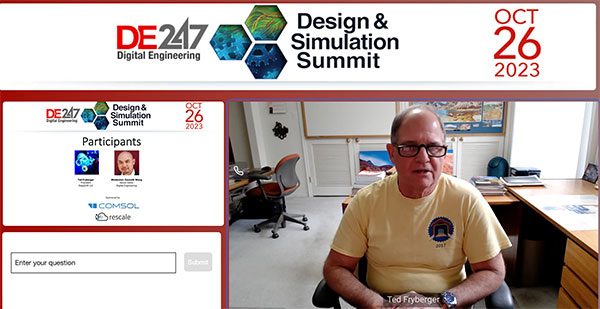
Ted Fryberger, president of DeepSoft in Columbia, MD, spoke on “Engineering Analysis: The Good, the Bad, and the Ugly.”
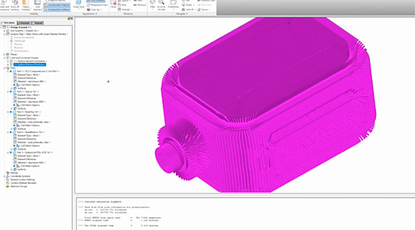
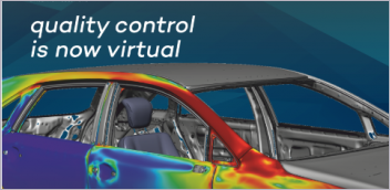
Ted Fryberger demonstrates use of Autodesk’s mechanical simulation software in modeling a part used underwater. Image courtesy of Autodesk and Ted Fryberger.
Latest News
October 31, 2023
The good and the not-so-good uses of analysis were the substance of a simulation session at last week’s virtual DE 247 Design & Simulation Summit. Just over 300 registrants logged on virtually for the talk, led by Ted Fryberger and moderated by DE’s own senior editor, Kenneth Wong.
Fryberger, seasoned with five decades of engineering experience and current president of DeepSoft in Columbia, MD, spoke on “Engineering Analysis: The Good, the Bad, and the Ugly.” He touched on best practices, what he calls “hard-earned lessons,” in conducting finite element analysis stress, thermal and dynamics analyses, and manual calculations. He shared what can advance or set back the analysis process. Essentially, Fryberger said he aimed to give a snapshot of “what practices help or hinder analysis productivity.”
His talk launched with a quick review of analysis tools accessible to engineers:
- Systems engineering: A big-picture view and analysis
- CAD/CAE: Create detailed geometry, for example, with 3D solid modeling
- FEA: all part/assembly geometry, material
- CFD
- Manual calculations: for examples, MathCAD, MATLAB
- Physical testing
- Simulation data management
To use FEA efficiently, Fryberger advises: “Purchase a high-quality FEA tool. As I like to say, ‘learn the best, forget the rest.’ Analysts must be proficient at manual analysis, general FEA and using a specific FEA tool. Analysts need powerful FEA tools, not design engineer solid model versions.”
His talk also highlighted analysis data setup tools, such as Excel, MathCAD and MATLAB.
To use FEA efficiently, Fryberger recommends the following quick tips:
- You need more than Excel.
- Use a math tool.
- Use a 3D controller to work faster.
- Create an analysis plan—“This is really important,” Fryberger notes.
- Use a project folder.
- Start with a linear static analysis first.
As important as the tools themselves are the people using them. “Managers, analysts and design engineers are a team—work together,” he suggests.
Though perhaps common knowledge to most, Fryberger shared the various FEA analysis types, noting how names can vary for different FEA software tools: static or dynamic (fixed magnitude loads); composites (complex with more failure mechanisms than metal or plastic); thermal analysis; CFD (a separate analysis software tool); electromagnetic analysis (also a separate analysis software tool); fatigue analysis; and multiphysics.
Commenting on composites as one of the FEA types, he advises, “Only use composites where there are real benefits.” Speaking to CFD, he says: expect a “steep learning curve.”
When working with CAD to FEA model problems, he notes that useful tools are available and recommends using such tools to create the geometry. “The best option is to use a 3D solid modeler to create all design geometry,” he says. “The worst option: FEA preprocessor geometry model creation—it’s like AutoCAD circa 1985—it’s that bad.”
In discussing CAD to FEA model problems, Fryberger explains that you’d want a “structurally significant model only—not all the design parts. Convert 2,500 design model parts into 100 structurally significant parts for FEA. Delete ALL unwanted parts. Don’t make the FEA tool think about 2,400 useless parts. This is all happening in the 3D solid modeler.”
Other points of note included an overview of FEA software components (preprocessor, solver, postprocessor); model element types (1D line elements, 2D planar elements/2D plate/shell; 3D solid elements); and boundary element types (springs and dampers, concentrated mass; rigid boundary element).
Delving into model element types, he says 2D plate/shell specifically is “the highest quality way to model thin wall parts—it is easy to change thickness; define single thickness property per part and change thickness without changing geometry.”
He also shared that an important best practice with 3D solid elements is that it’s important to note that you must have a minimum of 2 elements through thickness. You can quickly create huge models that won’t mesh or run. It’s less accurate than plate/shell elements,” he says.
When using model symmetry, he recommends noting the following:
- Model geometry must be symmetrical.
- Model loads are symmetrical.
- Model symmetry reduces model size, mesh and run times.
A major topic, according to Fryberger, is project folder structure. “A logical folder structure helps you divide and conquer,” he notes. “It helps you find your stuff.”
During the presentation, Fryberger, demonstrating capabilities of Autodesk Simulation Mechanical software, showed a yellow instrument that a diver would use. He highlighted the Von Mises stress (26,000 psi for sea water) and showed displacement in the 10-color spectrum. “Von Mises is good to use for combined stress,” Fryberger notes.
Fryberger offers an engineering analysis course that covers its wrinkles and problems unique to every product and analysis, as well as a 3-day course on introduction to FEA, which is FEA tool neutral. His areas of expertise are: FEA stress, thermal, and dynamics analysis; ocean & mechanical engineering design; C & C++ programming for engineering design, analysis, and real-time embedded programming.
This session (session 2: Simulation) was sponsored by Rescale and COMSOL. The Summit was sponsored by Dell and NVIDIA.
Subscribe to our FREE magazine, FREE email newsletters or both!
Latest News
Related Topics
All topics