Latest News
June 1, 2008
By Mike Hudspeth
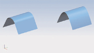 Figure 1: The surface on the left has a tangent blend. The surface on the right has a curvaturecontinuous blend. Which one looks smoother to you? |
A lot of design is about evoking emotion — primarily the emotions of your customer. We’re all familiar with the theory that form follows function, but does it? Is that all that your design is about? As an industrial designer I have to say no.
Function is certainly important but it is emotion that will sell, particularly in the realm of consumer products.
In part 1 of this two-part series of articles, we discussed how MCAD programs handle surface modeling. In this article, we’ll talk about the most frequently used surfacing tools chosen by designers and briefly describe those solutions most adept at taking the shape you’re trying to achieve — beyond the blocky forms of a solid modeler — into the stratified and “sexy” realm of the Class A surface.
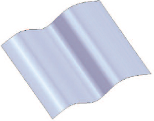 Figure 2: The extruded surface takes a profile and drags it along a specifiedvector. If the profile is wavy, the resultant surface will be too. |
Class A surfaces are generally defined as freeform surfaces of high quality. For the layman that means just about any surface you can see from the exterior, say, of an automobile.
There are many programs capable of making these surfaces, but we’ll get to them later.
Let’s Talk Geometry
When you create a surface you must be concerned with tangency and continuity. Tangency is when you have a surface that matches an adjacent surface exactly at only one place. Think of a fillet between two faces of a cube. Tangency is a measure of contact.
Continuity is a measure of smoothness. For geometry it is measured as having Gn continuity. G0 continuity means that the surfaces meet at only one place — they are tangent or coincident at the position of the joint, forming a sharp corner. G1 means they not only meet there, but share a tangent vector like a filleted edge. G2 means they share a common center of curvature at their joint in addition to being tangent. These are perceived by the human eye as smoother and more attractive (Figure 1).
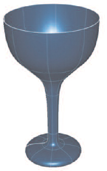 Figure 3:A surface of revolution is much less violent than it might sound. It is merely aprofile revolved around a specified axis. |
There are G3 and G4 also, but usually you only need to deal with G0 through G2. If you see a designation of C1, C2, etc. don’t worry. When something has G1 continuity the tangent vectors are parallel. When it is C1 the vectors are not only parallel but of equal magnitude. There is a lot of information about continuity available on the web. Here is one good source.
What Are They Actually Using?
As with any tool set there are always going to be certain tools that designers use more than others. The same is true for surfaces. I asked some of the top surface-modeling companies to describe for me the five most common surface types used in product design. I got some interesting responses.
1) The number-one type seemed to be the extruded surface. This is where you start with a profile — either a parametric sketch or explicit curves — and drag it through space along a single vector (see Figure 2). Imagine drawing a line with a pencil. Now, imagine drawing that line with a wide tip marker. Not only do you get the start, end, and every point between the two, but you also get every point across the width of your marker tip. You cover a lot of ground there.
2) The second most popular surface type was the revolved surface. This is where you select a profile and an axis and spin the profile around the axis to create a rounded object (see Figure 3). Imagine a wine glass or bottle.
3) The next most commonly designed surface type is the swept surface. In a nutshell, you take a profile and sweep it along another curve. There are all kinds of options you can apply that will give you different results. For instance, you can apply a scale factor along the length of the sweep that changes the size of the resultant surface.
4) Fourth on our list is the loft (see Figure 4). This is one of the most interesting types of surfaces and can result in some of the wildest surfaces. You select various profiles that represent what you want your surface to look like at a given place along its length. Imagine putting wire forms inside of a pair of pantyhose — the hosiery will take on the different shapes of the wires.
5) Last on our list is the point cloud surface (see Figure 5). This is basically where you have imported the results of a 3D scan that you can trace right over to acquire points in space. You then play “connect the dots” and draw the control geometry that will establish a geometric shape.
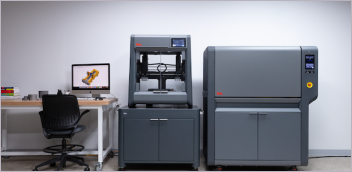
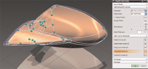 Figure 5: If you have access to a 3D scanner you can use real world objects to create digital, virtual models. Here, in NX, the user can use Rapid Surfacing to generate very accurate surface modelsthat can be used in the design process. |
So Who Does What?
About now I imagine you are probably wondering who the major players are when it comes to surfacing capabilities. These days there are quite a few. I will not list them all by any means (I’d have to write a book!), but here follows a short list.
Alias Studio from Autodesk has always been the industrial design community’s standard go-to program. It practically wrote the book on surfaces. There are very few automobiles (in fact I can’t think of any) that are designed without it. Companies use Alias Studio for the creation of Class A surfaces. Remember, those are the surfaces that you see when you look at an automobile. They are the really important surfaces — in the eyes of car buyers — and they have to be perfect. Alias is a surface-only modeler, so if you want to go into solids you’ll have to translate your surfaces into something else. And while Alias might only do surfaces, it does them really well.
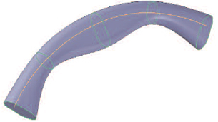 Figure 4: A lofted surface uses multiple cross-sections to define the shapeof a surface. These are good for complex shapes. |
But while Alias still pretty much rules the roost in industrial design, others are giving the program a run for its money. The first major Alias competition I saw was ICEM Surf. This is also a surfaces-only application and has been associated with Pro/ENGINEER for years. Rhinoceros, from McNeel North America, is a lower-cost alternative. McNeel came out of the blue with this amazingly powerful product that just keeps getting better. Unlike Alias, Rhino does solids as well as surfaces, and it really doesn’t make a distinction between the two. I like that. It keeps things easy to understand.
NX from Siemens PLM Software (formerly UGS) has always had surfacing capability. A few revisions back NX developers decided to beef up its surfacing capability to take on Alias for the industrial design market. The same company also makes Solid Edge, which has long been known for its mechanical design tools, but does some pretty nice surfacing, too.
Delcam PowerSHAPE makes great use of bitmapped images for things like embossing. With this application you can import an image and then wrap it to visually bump out (or in) very complex patterns indeed — patterns that would be tedious or too time consuming to model directly.
I think if I had to cite a program that is making the most inroads on Alias Studio in the industrial design market it would be SolidWorks. SolidWorks does some very nice surfacing with such things as swept and lofted surfaces. Design firms are finding its combination of reasonable price and wide range of capabilities attractive.
PTC’s Pro/ENGINEER Interactive Surface Design Extension (ISDX) has added surfacing to its parametric solid modeling capabilities, replacing its old standby ICEM Surf. High-end CATIA is popular in the aerospace industry. It is used for aerodynamic surfaces and the transitions from appendages to the fuselage.
There is also VX, which has a lot of power for the price — especially in the model-healing arena; IronCAD, which has two modeling kernels, ACIS as well as Parasolid so as to broaden its capabilities; and Think3, which is frequently used for industrial design. Think3’s biggest claim to fame is Global Shape Modeling, a capability that alters the overall shape of the model as a whole. Finally, among the most popular surfacing tools, are formZ from AutoDesSys — with a fairly complicated interface that proves worthwhile once you get used to it — and solidThinking, pretty popular in Europe and available for the Mac, and, as its name suggests, does solids, too.
The End Result
In 3D modeling you have a virtual toolbox. It is filled with tools (commands and functions) that you can use to build what you design. I encourage you to fully investigate and experiment with each of your tools so you can know when to use what and why. It’s the only way for you to avoid becoming pigeonholed into using just the same four commands you’ve always used and getting the same old boring results. Surface modeling is a great and fast way to achieve stunning results. That’s why it’s been a mainstay in the industrial design community. That’s why it needs to be used in engineering. Give it a try. You’ll be glad you did.
Information:
Autodesk, Inc.
San Rafael,CA
AutoDesSys
Columbus,OH
Dassault Systemes
Paris, France
Delcam
Salt Lake City,UT
Icem
Southampton,UK
Ironcad
Atlanta,GA
McNeel North America
Seattle,WA
PTC
Needham,MA
Siemens PLM Software
Plano, TX
solidThinking, Ltd.
Vicenza,Italy
SolidWorks Corporation
Concord,MA
Think3.com
Casalecchio di Reno (BO), Italy
VX Corporation
Palm Bay,FL
Mike Hudspeth, IDSA, is a senior designer for a global medical company and has been using a wide range of MCAD products for more than 20 years. He, his wife, two daughters, and their cats live outside of St. Louis, MO. Send him an e-mail about this article to de-editors@digitaleng.news.
Subscribe to our FREE magazine, FREE email newsletters or both!
Latest News