Latest News
May 1, 2008
By Mike Hudspeth
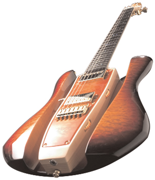 Figure 1: While surfaces may not have any thickness, they can have really cool 3D shapes like thisDave Mason limited edition beauty from RKS Guitars modeled in Alias Studio. |
A 3D solid modeling solution can be the best tool you have in product development. When you are engaged in modeling designs in an MCAD program you aren’t merely depicting the exterior shape of the product, what you are actually doing is building it digitally. It’s an important concept. In the “good ole days” you would have had to draw 2D representations in orthographic views (straight-on views usually separated and rotated 90 degrees to each other). But those views were only as good as your imagination.
It was rare to meet a designer in industry who thought in 3D, so it was always a roll of the dice whether the views were drawn correctly. Even a lot of drafters have trouble with it. But when you model in 3D you aren’t interested in 2D representations. You are actually building the part. You can rotate it, measure it, in short, you can really get to know it. It’s a better way, but it’s not always the easier way.
Sometimes when building a 3D solid model you can come up with a shape that causes fits. A lot of solid modelers don’t really handle organic shapes well. Sure, angular, welded steel beams are a cinch, but try creating a car body with silky smooth curves. Most 3D solid modelers can get close, but they are limited to commands like extrude, revolve, blend, etc. You sketch something then extrude it a distance, then Boolean it with something else. You’re left with very blocky models.
According to VX Corporation, “In order to provide a reasonable set of operations, solid modelers typically restrict the user to a finite set of shapes (i.e., spheres, boxes, etc.) and/or procedures (i.e., extrude, revolve, sweep, fillet, etc.) that can be used to define the geometry of the object. This inherently limits the range of objects that can be described. In addition, they do not allow the representation of zero thickness partitions, such as the parting surface of a mold. Because solid modelers require that a true bounded volume be described at all times, manipulation and ‘fine-tuning’ of the individual bounding faces is generally restricted.”
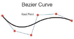 Figure 2: A typical NURBS surface uses Bezier curves to define the shape of the surface. The knot points of the curve are “weighted,” so movingthem affects the curve. |
Wouldn’t it be nice to be able to go beyond, to create truly biomorphic shapes? Well you can! You just have to use surfaces.
What is it?
When computers were first used for drawing they used basic text entry to establish x and y coordinates from a given origin (0,0). This is known as a Cartesian coordinate. If you wanted to identify a specific point you plugged in the numbers for how far it was from 0 along both the x axis and the y axis. Later, the z axis was added and 3D was born. If you wanted a line, you established two points in space. A line is a beginning point, an ending point, and every point that lies directly between them. When you start drawing closed polygons you start to get into the surface arena. The surface is all the points that make up the perimeter of the shape plus every point that lies inside. By definition, a surface has no thickness. If you want to get technical, there is no such thing as a surface in nature. Sure, you can get really thin, but there will always be thickness. A surface is a theoretical object. But it’s not just a flat object. Surfaces can have wonderful 3D shapes (see Figure 1). And if you put a bunch of surfaces together such that they enclose a volume of 3D space — and establish what is inside and what is outside — you have a solid. You can build some incredible geometry, but 3D solid modeling is not enough.
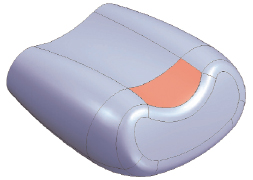 Figure 3: Sometimes you are faced with open holes in your model. Using surfaces you can not only patch them up but match the curvature of the surfaces adjacent to the patch. This example from Solid Edge could technically be called a mesh surface because it has four sides with edgesacting as sections and rails. |
The main advantage to using surfacing is that you can literally model anything you can imagine. There are different types of surfaces: Nonuniform rational B-splines (NURBS), meshed, faceted, etc. The basic NURBS surface uses knot (or control) points on Bezier curves to define the shape (see Figure 2). This is the most accurate and controllable type of surface.
A meshed surface (which can also be pretty accurate) might use splines as well, but it doesn’t have to. A mesh surface typically has four sides with curves that describe the two ends (or sections) and the sides (or rails) (see Figure 3).
If you have only three straight sides for your surface you are likely to have a faceted surface. Faceted surfaces are made up of triangles of different sizes (see Figure 4). Think here of an SLA or VRML file. These are great for stereolithography or web graphics, but are sadly lacking for precision modeling.
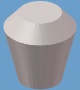 Figure 4: A faceted surface is made up of lots of little triangles of various sizes. You might have to look closely to see these. The size of the triangles depends on how tight your tolerances are. This image was generated using SolidWorks. Figure 4: A faceted surface is made up of lots of little triangles of various sizes. You might have to look closely to see these. The size of the triangles depends on how tight your tolerances are. This image was generated using SolidWorks. |
What’s it do?
When you’re modeling, it’s not only the surface itself that you have to think of. You have to think of the interactions between the surfaces and all their edges. When I was on the drafting board (yes, there are still a few of us around who remember those days), drawing a line intersection meant crossing two lines until they appeared to intersect. I actually knew drafters who did the same thing when they went into CAD. If the lines looked close enough to an intersection they called it good (see Figure 5). But when we went to 3D modeling those ersatz intersections made creating a section perimeter nearly impossible. They would always be just far enough apart to gum up the whole works. I had to come in and trim everything before any real work could be done. It was a headache.
Just like you can’t expect to create a clean and fully functional model if you don’t have everything trimmed properly, you also can’t expect to do a lot with a model whose surfaces have big gaps and open holes. For example, take a look at imported geometry.
|
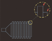 Figure 5: I should hope everyone reading this magazine knows that snaps are the way to go when trimming one entity to another. If you don’t use them, you can get what lookslike an intersection but isn’t.
Now, some translators are better than others, but almost all of them will, from time to time, drop out a surface or conflict when it comes to tolerances. Sometimes a surface forgets how it’s trimmed and expands into something that overlaps the boundaries the original creation program put on it. The receiving program either has to try to figure out how to trim it — or more often ignores it. And if your tolerances aren’t set up correctly, you can easily find gaps. It happens because one program is looking for things to be more accurate than the other is set to be. The first program says two surfaces meet, plus or minus 2 percent, and the second program is looking for it to be within 1 percent. Both are technically correct, from their point of view, but one will see a hole where the other does not. Either way you aren’t going to enjoy the results. That’s when you need to start the healing process. Healing is when you go into your geometry and find the places that need to be fixed and then fix them. Many programs are good for this. I know that VX in particular has some very powerful healing tools. But we’ll get into that later.
In the second part of this article, we will get into what is available out there for good surface design. We will talk about the most commonly used surfacing commands and what programs do what.
Info More:
Alias Studio
Autodesk, Inc.
San Rafael, CA
Solid Edge
Siemens PLM
Plano, TX
SolidWorks Corp.
Concord, MA
VX Corporation
Melbourne, FL
Mike Hudspeth, IDSA, is a senior designer for a global medical company and has been using a wide range of CAD products for more than 20 years. He, his wife, two daughters, and their cats live outside of St. Louis, MO. Send him an e-mail about this article to de-editors@digitaleng.news.
Subscribe to our FREE magazine, FREE email newsletters or both!
Latest News