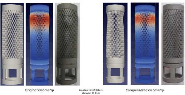
With complex structures for 3D printing as shown here, print process simulation and distortion compensation are part of the design process. Image courtesy of Ansys.
Latest News
May 15, 2020
To those who work on injection-molded parts, distortion compensation is a familiar concept. These engineers learn to adjust their CAD geometry to compensate for the anticipated shrinkage that occurs when the liquid cools down inside the mold.
As more manufacturers explore additive manufacturing (AM), they’re quickly learning that the same distortion compensation protocols, but with much greater complexity, play a critical role in design for AM.
Print materials and processes are the two primary factors that determine the nature of the distortion. The added complication in AM is the need for support structures. Certain fixtures must be added to the geometry to keep the part propped up in the print chamber during the print process. Because these supports aren’t part of the intended design, they must also be removable.
All these considerations can discourage newbies from taking a stab at AM. But the good news is, many leading AM-specific design software packages have automation tools to help you shape the geometry to fit the intended print process.
Intersection of Machine, Material and Physics
Simulation software maker Ansys offers the ANSYS Additive Suite, which specifically targets metal AM. Capabilities include thermal simulation, topology optimization, AM process simulation, and geometry editing and modification.
“Distortion compensation is one of the top reasons customers use our ANSYS Additive Suite,” says Brent Stucker, director of AM for Ansys. “The method is always machine- and material-specific. What you are doing is figuring out how the geometry will change during the production process, then modifying the geometry to account for that change using an algorithm.”
Stucker explains that, in a typical workflow, the user prints a test part, measures the critical dimensions to ascertain the discrepancies, then uses the data as input for the software to calibrate distortion values.
“If you print a reference part with simple geometry, you can measure the differences using a caliper,” says Stucker. “For parts with sweeping curves and intricate geometry, eyeballing where to place the caliper might be a problem. That’s where scanning is helpful.”
As part of its distortion calibration, Ansys’ software incorporates machine behaviors provided by 3D printing system makers, and material characteristics from material suppliers. Accurate distortion prediction is facilitated by the simulation software’s ability to digitally recreate the thermochemical changes that occur in the print process, based on the data from hardware and material makers.
Non-Uniform Distortion
With 3D printing, the orientation of the part—the way the part sits on the print bed while it’s being printed—affects the distortion type. The changes that occur in the Z direction, for instance, are not necessarily the same as what happens in the X or Y direction. This has to do with, in part, the different heating, cooling and compression forces the part endures in different directions based on its position.
“It won’t help to simply scale a part uniformly in all directions,” says Maoz Barkai, 3DXpert product manager for 3D Systems. “With powder bed printing, the cooling that happens in the Z direction is offset by the powder buildup during the print process. So you may only need to scale your part in the X and Y direction.”

The plug-in 3DXpert for SolidWorks lets you analyze and optimize your CAD parts for 3D printing. Image courtesy of 3D Systems.
3D Systems offers 3DXpert for SolidWorks, a plug-in to help SolidWorks software users design and simulate parts destined for AM.
“A click of a button in SolidWorks brings your native CAD data directly into 3DXpert for SolidWorks and provides you with an extensive toolset to easily analyze, prepare and optimize your design for additive manufacturing. Once completed, the ready-for-print data can be sent to any printer or back to SolidWorks,” the company writes.
As a hardware maker without proprietary simulation technology, 3D Systems uses Amphyon software from its partner Additive Works for process simulation. According to Additive Works, the software focuses on laser beam melting processes commonly used for metal 3D printing.
Cell Growth and AM
AM system maker Desktop Metal’s Live Parts software uses morphogenetic principles based on cell distribution to generate suitable AM parts. The company also provides Fabricate software to prepare and print metal AM parts in its office-friendly Studio System hardware.
“In metal, if you use binder jet or powder bed technology, you may end up with the need for post-processing. Typically, you need sintering to transform the printed part into a dense solid metal part, so you need to think about not only the effects of the print process but also the sintering process,” explains Andy Roberts, VP of software, Desktop Metal.
“If you use laser printing, you are essentially baking the part, so there’s no need for sintering, but you need to think about the huge temperature gradients the part needs to be subjected to. These affect the shrinkages in non-uniform ways,” he adds.
Roberts feels that the intimate knowledge his team has as hardware developers, and the tight integration between Desktop Metal’s hardware and software, make their distortion prediction much more reliable.
“We know, for example, exactly how long it takes for the material flowing through the nozzle to stop after you pushed the stop button,” he says.
For support structures, Desktop Metal employs a patented system of Separable Supports, introduced in 2018. The system “enables users, for the first time, to print large metal parts with complex geometries that can be easily removed from their support structures by hand or to print metal objects with separable interlocking structures,” says Jonah Myerberg, CTO and co-founder of Desktop Metal.
Another potential problem in design for AM, ANSYS’ Stucker points out, is blade crash—the collision between the printer’s powder handling mechanism and the part itself. “Our software allows you to identify potential blade crashes, a feature other software packages might not have,” he says.
Ultimately, distortion compensation is an algorithm-driven approximation. “With materials that are well-defined and processes that are well understood, we can eliminate 95 to 98 percent of the distortion problems,” says Stucker. “Even with outlier geometry involving anomalies, we’re still eliminating 85 to 95 percent of the issues.”
From Mesh to Parametric
Once the distortion-compensated geometry is printed and verified to satisfy the required specs in form and function, companies should keep an archival copy. Whereas classic CAD programs work in formats defined by mathematics (lines, arcs and parameters), simulation software typically works in mesh models and tessellated geometry.
This is where Stucker feels Ansys has an advantage over some of its rivals.
“We use our SpaceClaim technology as the translator, so you can easily bring that distortion-compensated model back into your CAD package,” he says.
Different from a mesh model—which is not easily editable in CAD programs—the SpaceClaim-translated model will be editable in standard CAD tools, Stucker points out.
ANSYS acquired SpaceClaim, a direct-modeling software developer, five years ago. The technology is useful for editing a wide range of native CAD geometry without using the original authoring package itself.
“We worked hard on the transition to make it smooth. With our software, we map the changes [distortion compensation] back onto the original CAD model so you can keep that for your record,” says Stucker.
Editor’s Note: For more on this topic, also check out “Bridging CAD to Additive Manufacturing” in the April issue.
More 3D Systems Coverage
More Ansys Coverage
Subscribe to our FREE magazine, FREE email newsletters or both!
Latest News
About the Author
Kenneth Wong is Digital Engineering’s resident blogger and senior editor. Email him at kennethwong@digitaleng.news or share your thoughts on this article at digitaleng.news/facebook.
Follow DE