MSC Software’s Apex CAE software constantly re-assesses and meshes the geometry in the background to keep up with the user’s edits and changes. Image courtesy of MSC Software.


Latest News
May 2, 2016
 MSC Software’s Apex CAE software constantly re-assesses and meshes the geometry in the background to keep up with the user’s edits and changes. Image courtesy of MSC Software.
Almost everything in meshing—subdividing a 3D model into thousands of tiny geometric elements in preparation for finite element analysis (FEA)—is about weighing the pros and cons. If the model contains a high level of details (like rounded corners, holes, bolts and nuts), the computation required to mesh the geometry may take longer than necessary, or (worse) bring the hardware to its knees. The alternative is to reduce the amount of details, but that alternative carries its own risks. If you’re not sure which features are critical to the analysis, you could accidentally compromise the accuracy of the simulation by removing what should be included.
Some simulation software takes the burden off the user with full or partial mesh automation. Because it requires fewer expertise-driven decisions, this approach allows a wider range of users, including novices, to perform a greater volume of simulation. However, such automation is achievable only if the software is allowed to make sweeping generalizations in its treatment of the geometry. For those seeking a simple design validation (for example, is this three-legged chair strong enough to support a person weighing 250 lbs.?), this may be acceptable. For others seeking to squeeze the last gram of weight out of an airplane part already heavily edited, this may not be the right approach.
To improve the meshing process, some software developers come up with new algorithms to tackle complex, organic geometry well beyond the bounds of classic mechanical shapes. Others propose using the detailed model, not the simplified geometry, for better accuracy. A few even propose skipping meshing altogether and performing FEA directly on the CAD geometry itself. The solutions and strategies featured in this article represent a small sampling of the latest thinking in the mesh-making frontier.
Hex Mesh for Bones and Brains
In its early days, additive manufacturing (AM) was a prototyping method, but the more mature AM technologies of today are well on their way to becoming viable manufacturing options. AM can build biomimicry-inspired design like organic shapes and honeycomb structures previously dismissed as impractical or too costly to produce. So simulation and analysis technologies, too, have to keep up. One area where such irregular shapes can present a challenge is in automated meshing.
According to csimsoft, the traditional pave-and-sweep method “[decomposes] the model into sweepable volumes,” which “sometimes takes hours or days to prepare.” Paul Ressler, csimsoft’s director of Sales and Marketing, explains how Bolt deals with irregular shapes: “We use a grid overlay—we build a bounding box around the model, create a Cartesian grid, and cut away everything else outside the model.” The key to its approach, he added, is “the algorithm that creates high-quality hex meshes at the surface.” That means generating meshes for bones and brains without cutting them up, in a manner of speaking.
By user request, csimsoft is now developing what it calls “adaptive meshing,” capable of capturing fine features, like sharp edges. “This will have the ability to snap to features and capture very precise edges,” explains Ressler.
Does Meshless Analysis Use a Mesh?
When SIMSOLID debuted its commercial release in early 2016, the company announced that SIMSOLID “eliminates geometry simplification and meshing, the two most time consuming and expertise-extensive tasks done in traditional FEA.”
Previous to launching SIMSOLID, Ken Welch held executive roles at MSC Software and Moldflow. “Our method does not create a mesh. It works directly on the fully featured CAD model. Defeaturing is not required,” he says.
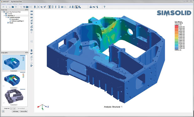 SIMSOLID works directly on the fully featured CAD model, and therefore does not need to defeature, the company points out. Image courtesy of SIMSOLID.
Some argue so-called “meshless FEA” actually does use a mesh, but hides the process from the user. “If you’re talking about isogeometric analysis, also called meshless, you still need a coarse mesh in reality. There is always an underlying mesh whether you see it not,” says csimsoft’s Ressler.
John Chawner, president of Pointwise, says: “A method could be deemed meshless if a mesh is generated without the user knowing. There are also numerical techniques for solving field equations that are called mesh-free because they work on a cloud of points without connectivity, but they still rely on some sort of organization of the points to be able to compute derivatives of the governing field equations.”
SIMSOLID’s Welch clarified that SIMSOLID’s method is not the same as isogeometric analysis. “Historically, structural FEA have used simple linear or quadratic elements to represent the geometric domain and to associate simple basis functions with the mesh nodes. Then, P-elements drastically changed the requirements for domain discretization by increasing the polynomial level of basis functions. This allowed elements with much larger aspect ratios and distortion. SIMSOLID is the next step in this evolution in that it drastically changes the discretization requirements by associating basis functions with a variety of geometry supports in form of volumes, surfaces, lines and point clouds. They are distributed in the part volume and adapted to part geometry on the fly during the solution phase. This provides the ability to handle geometrical imperfections, as well as assembly contact imperfections like gaps, penetrations and ragged contact areas. While classical finite elements are not created, in terms of formulation SIMSOLID is equivalent to FEA in that it uses the same variational principles,” he says.
Automatic Repair and Simplification
Geometry cleanup and repair is often the prelude to meshing, because flawed or imperfect geometry usually results in mesh failures. Most simulation software has a way of identifying and flagging problematic geometry during CAD data import.
“There are many well-known defects in design geometry that can be identified before meshing starts,” Chawner explains. “Some of the obvious defects to look for are sliver or degenerate geometry, duplicate geometry, and missing geometry. There are less obvious potential problems such as odd parametrizations of the geometry (speaking specifically here about NURBS). In Pointwise, we take several actions on geometry import up to and including assembly of the geometry into solid models that have allowed the user to go right from geometry import to meshing.”
The next step, defeaturing, involves removing small details not critical to the simulation. Automating this portion is trickier. Chawner says the degree of automatic defeaturing possible depends on the requirements placed on the geometry by the meshing technique, the intended use of the simulation, the source of the geometry, and even the phase of the design process you’re in.
“Imagine the extreme case of a full-scale submarine, which by most CFD definitions is a very large object,” Chawner says. “The Reynolds number of the flow requires a very small near-wall spacing to resolve the boundary layer. Now magnify that by creating an outer boundary around the submarine that’s multiple body lengths away. The length scales are now pushing what can be done accurately with double precision floating point operations. Now consider how to deal with tolerancing the gaps between adjacent surfaces in the submarine geometry.”
Welch says SIMSOLID is able to bypass defeaturing because it is tolerant of geometric and contact imperfections.
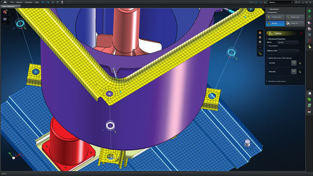
Background and Local Meshing
In 2014, MSC Software launched its Apex software. It supports automatic geometry repair and geometry simplification, plus it constantly regenerates meshes in the background. Hugues Jeancolas, MSC Apex’s senior product manager, says: “Mesh regeneration operations are managed by the Apex generative framework, which is optimized for performance and aims at only regenerating local portions of the mesh that are affected by a change.”
With some simulation software, a new mesh needs to be regenerated for the entire model every time something changes in the design, even if the change is confined to a small region of the entire design. In such an environment, the computing penalty for design changes can be high.
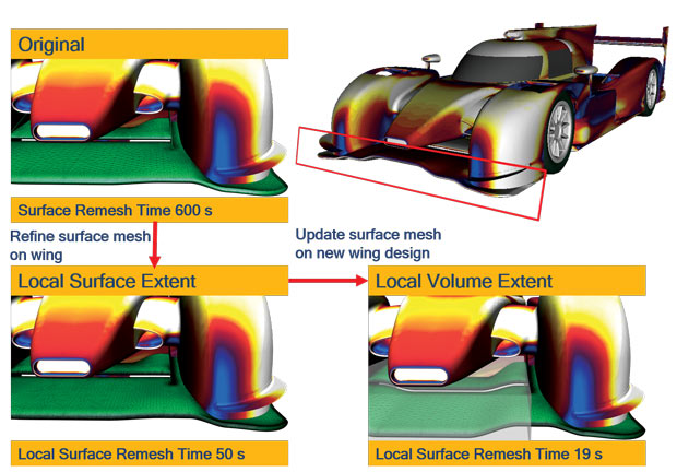 The latest release of STAR-CCM+ comes with a feature called Local Surface Remeshing, which allows the user to choose what is remeshed. Image courtesy of CD-adapco.
In the latest release of its STAR-CCM+ software, CD-adapco tackles this with what it calls “Local Surface Remeshing.” In a recent blog post, James Clement, STAR-CCM+ product manager, wrote: “Local Surface Remeshing will allow the user to choose what is remeshed, be it a single surface or most of the model, and it will only change the mesh in the area specified by the user. To me this means I can spend more time getting engineering results and less time waiting for a mesh to finish.”
The Ongoing Debate with Meshing: Hide or Expose?
NASA’s “CFD Vision 2030 Study: A Path to Revolutionary Computational Aerosciences” asserts that “the mesh generation process should be invisible to the CFD user.” Chawner ponders: “Invisibility is something even an expert analyst would love to have. Unfortunately, meshing is often a lot more visible than we’d all prefer. Some would say it’s not just visible—it’s up in your face.”
Chawner also cautioned the automated meshing procedure wouldn’t be of much help to the user if “it fails quite frequently and when it fails, the user receives no feedback on how to fix it. That’s a complete dead end.”
There may be a happy medium if the automated systems are designed and implemented by experts in meshing, simulation, and the domain of application. “Those systems should have limits on their applicability that are well known through validation and verification and well communicated to users,” Chawner says.
The meshing needs of different application domains such as CFD and structural mechanics are vastly different, Welch says. “For structures, a tightly integrated method that closely links model preparation, analysis and automatic solution refinement is a more efficient and robust way to approach the problem,” he says. “By controlling the entire simulation workflow, more automation is possible than with a loosely coupled mesh-solve approach.”
Some experts see hope for success in template-driven, app-like simulation for well-defined, repeatable scenarios. For example, simulation apps for turbine blades or transport aircraft with wings. “The simple act of narrowing the field of application vastly improves the odds of automating a system,” Chawner reasons.
More Info
Subscribe to our FREE magazine, FREE email newsletters or both!
Latest News
About the Author
Kenneth Wong is Digital Engineering’s resident blogger and senior editor. Email him at kennethwong@digitaleng.news or share your thoughts on this article at digitaleng.news/facebook.
Follow DERelated Topics