
Latest News
June 1, 2018
Waiting is an essential part of simulation—or so it seems. The typical workflow with simulation is: you set up your job, press run, then go make a cup of coffee or grab lunch while your workstation does the number crunching. Depending on the complexity of the job, the wait could be a few minutes, hours or days. Many engineering firms and design shops that rely heavily on simulation develop workarounds to avoid the wait. Scheduling simulation jobs to kick off after hours or over the weekend is one way.
But the launch of ANSYS Discovery Live and a few other simulation programs suggests, for products targeting the non-expert crowd, near-instant feedback can be delivered using simpler calculation, parallel processing and mesh automation. The trade-off—speed over accuracy—is the subject of discussion among many engineers.
Instant Design Exploration
The simulation software industry’s overtures to the designer community usually come in one of three forms: CAD-integrated simulation (simulation tools nested inside a CAD package); simplified simulation (simulation with a simpler interface and fewer choices); and app-style simulation (template-driven simulation apps that address specific scenarios).ANSYS’ latest offering, ANSYS Discovery Live (ADL), falls into the second category, but with a twist. The emphasis is not only on simplicity, but also speed.
“This instant, interactive simulation environment allows engineers—at all levels and in every discipline—to explore their concepts and designs,” the company claims.
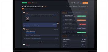
 Targeting the designers, ANSYS Discovery Live uses a simplified user interface and automation to speed up simulation, resulting in near-instant feedback. Image courtesy of ANSYS.
“There’s no preprocessing, no post-processing. Results are real time. You can change direction or the size of your forces, edit your geometry or change materials, and interactively get updated results,” says Mark Hindsbo, VP and GM of ANSYS.
Part of the speed comes from the incorporation of direct editing—a technology ANSYS acquired from SpaceClaim in 2014. Different from parametric editing, direct editing (or push-pull editing, as some call it) allows designers to make geometric changes quickly without concerns for the part’s parametric history or the feature. Incorporating it into ADL allows the simulation user to edit the targeted geometry inside the simulation environment, avoiding the round trip back to CAD that’s usually required. For instance, if you have just completed stress analysis for a bar stool with three legs, but now wonder how the design might perform with longer legs or a wider seating area, you can edit the geometry inside ADL without going back to the CAD program you used to create the stool.
The other part of the speed comes from graphics processing unit (GPU) acceleration, the use of the GPU’s parallel processing power to speed up computation. “We wrote solvers from the ground up on (NVIDIA) GPUs. Where others might augment compute power on GPUs, we did it natively, embracing its massively parallel nature. Modern PCs have thousands of cores on their GPUs versus a handful of CPU cores. In the process, we had to invent new numerical and computational algorithms,” says Hindsbo.
Simpler Choices, Hidden Meshes
The simplicity in ADL’s user interface (UI) is a departure from other products by ANSYS, which offer users a lot more menus and choices to allow complex simulation scenarios.“We designed ADL for rapid concept exploration, not high-accuracy design validation,” Hindsbo explains. “As a result, we do not expose anything in the software unless we can do it in a simple, easy-to-use way that our casual simulation users will love. For example, complex physics decisions such as time-step size and convergence criteria do not appear in the software and are instead decided dynamically by the technology based on the model, boundary conditions and current simulation results. We believe this dynamic and adaptive approach to be key to making simulation accessible for every engineer.”
The conspicuous absence of certain simulation steps—such as meshing—may surprise some ADL users. That is intentional, according to Hindsbo. “The people who want to tweak meshing parameters are usually experts,” he points out.
Automating and delegating these functions to the background contributes to the simplicity of the UI, where the user doesn’t need to decide the type of mesh to use or the appropriate density. In higher-end ANSYS products, this tool is open to the users, as experts generally understand the correlation between such choices, and like to control the accuracy as desired.
Fully automating the meshing process or skipping it altogether might have been an unthinkable proposition five or six years ago, but a few simulation software titles now promote it as part of its strength, especially in its appeal to the designers. CAE software industry veteran Ken Welch describes its product SIMSOLID as meshless simulation.
“The bottom line is that these CAD-to-Mesh steps require many judgment calls, are labor-intensive, error prone and require experts in both simulation and CAD,” Welch says. “We are pioneering new methods that work directly on fully featured CAD assemblies and do not create a mesh. With this, you can work lockstep within your design process to quickly and efficiently analyze the original CAD geometry without modification or simplification.”
With SIMSOLID, typical run times only take seconds to minutes, even for large assemblies, according to Welch. It works on standard computers and does not require additional high-performance computing (HPC) or GPU hardware. The program also provides a broad set of analysis capabilities including unique real-time transient dynamics, he says.
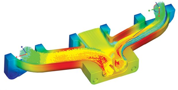
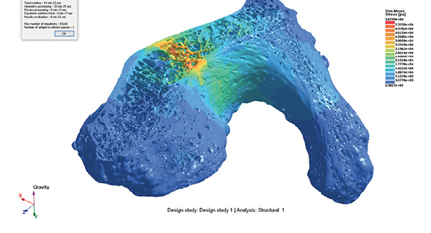 SIMSOLID speeds up the simulation process by skipping the meshing process altogether, resulting in faster solving time. Image courtesy of SIMSOLID.
The company csimsoft, which specializes in geometry preparation and mesh generation software, offers what it describes as push-button mesh generation in Bolt. “Bolt is a push-button solution for generating all-hex meshes from complex geometries with little or no user interaction,” notes csimsoft. Bolt also offers tools to isolate mesh elements beyond the desired value, make adjustments to the cell-generation setup, and remesh the geometry for better accuracy.
The degree of mesh controls to expose or hide remains a difficult balance for simulation vendors hoping to attract non-experts. Whereas experts possess the necessary skills to decide on the right mesh type, the level of resolution and the regions of the geometry that need special attention for a particular job, most designers may not be equipped to make these judgments.
Interactive Moldflow
Computational fluid dynamics (CFD)—the solver technology for simulation and analysis of airflow, heat flow, liquid flow and other types—is considered a compute-intensive process, due to the amount of calculation involved in predicting the complex flow patterns. The technology has proven to be a staple among plastic product designers, who need to study the injection molding process to ensure manufacturing success.“We began looking at interactive response in this area because we want to give people who study plastic design real-time feedback,” says Brian Frank, senior product line manager for Simulation and Analysis Solutions, Autodesk.
Ten years ago, Autodesk forked over approximately $297 million to purchase Moldflow, which develops special software to simulate how plastic parts are manufactured. Today, Autodesk Moldflow is a leading plastic mold design simulation package.
“One way to compute as quickly as possible is to rely on the GPU to break the problem down so it can be computed in parallel,” says Frank. “The other is to limit the input the software asks from the engineer or the designer. Mesh sizes and voxel types are also automated so the user doesn’t need to understand it. The software uses rules and assumptions to account for what’s not asked, in order to reduce the complexity of the problem.”
Moldflow users can reposition the mold inlets and outlets in their design or make alterations to the geometry and obtain the updated flow patterns with near-instant feedback, Frank points out.
The same interactive response was also in a product formerly called Autodesk Flow Design, for virtual wind tunnel testing. The product is no longer sold individually, but its components are now found in the company’s core mechanical design package Autodesk Inventor and architectural wind-load analysis products.
Generative Design with Real-Time Response
The same interactive response can be a far more powerful tool when implemented in one of Autodesk’s pursuits, generative design software, according to Frank. “We’re looking at the next step, where we want the software to inform your design decisions. It’s the aided part of the computer-aided design,” he says.Generative design, some argue, is the next step in simulation. Standard simulation programs can verify the performance of a design submitted by the user. By contrast, generative design software can propose various design alternatives based on user-provided parameters, such as loads, stress and pressure.
Currently, much like typical simulation, generative design requires the user to set up the job, then wait for the computation to complete. The so-called generative response is not instantaneous or in real time. But Frank believes this will soon change.
“We’re getting close to it. We’re doing some really complex things mathematically. If we continue to push the boundaries, apply the same techniques as simulation and partner with the hardware vendors to eke out performance in memory management and parallel processing, we’ll get to near-real-time feedback,” he says.
Growing Parts in Real Time
3D printing system maker Desktop Metal’s software Live Parts is among the growing number of simulation programs that cater specifically to the additive manufacturing space. Whereas most topology optimization software focuses on removing materials (to create a lighter product), Desktop Metal’s Live Parts takes the opposite approach. It begins with a blank space, then grows materials only where necessary to create the optimal design.“It’s not using traditional FEA [finite element analysis] or CFD. Rather, it’s based on modeling a cellular organism that grows from seed cells into an embryo and finally a mature structure that meets the requirements of the part. It uses the GPU to dramatically speed up the growth and physics processing so that it operates in real time,” explains Andy Roberts, the creator of Live Parts.
In its demonstration videos, Roberts is able to change forces and loads in the middle of a simulation session (or, to be more precise, a cell-generation session) to obtain near-instant feedback from the software. Live Parts is currently in beta, part of Desktop Metal Labs.
“Live Parts is hosted in the cloud on a pool of GPU-accelerated virtual machines (VMs),” says Roberts. “The application leverages 2,500-3,000 core GPUs running in parallel on each VM to perform thousands of cell-level calculations and multiphysics simulations in real time, enabling support for rigid and elastic bodies, fluids, cloth and more. Users can access Live Parts by connecting to a VM from most internet-enabled devices through the browser or through a downloadable client that runs locally. The software sends a graphical representation as a video stream in real time to the users’ local device, ensuring a consistent and high-quality experience regardless of local device specifications.”
Cool Visuals or Practical Use?
The real-time feedback in simulation and some generative design software unquestionably makes for impressive presentations, as a way to help ordinary folks understand the engineering and design issues on display. But does the interactivity serve any practical purpose?“[In Autodesk simulation products] it’s a useful tool to understand at the high level how things behave and react to one another,” says Frank. “What we often hear from users is, ‘this is a very good way to understand how we may want to set up a higher-level simulation problem.’”
“In [Desktop Metal’s] Live Parts, we wanted to enable parts to grow in a life-like environment in which forces change dynamically and the part is able to react to these changes as it grows,” says Roberts. “This interactivity also makes it possible for users to modify physics inputs and see how their designs react immediately. This allows users to better understand cause-and-effect relationships between constraints and designs more easily, enabling faster design iteration and shortening the cycle from design to manufacture.”
To a large extent, the instant or near-instant feedback is possible on the current generation of hardware only in simplified simulation runs, the type that caters to designers working at the front end of the process, or the conceptual phase. For more sophisticated simulation, instant feedback requires parallel processing on a cluster or in the cloud.
Approximate Answers
In the early design phase, users tend to seek general design guidance; therefore, approximations can be employed with little or no detriment. “The Discovery Live applications makes smart assumptions and defaults so you can get started immediately. The user can then subsequently make refinements or override defaults, but they don’t have to specify every single parameter before getting results,” says Hindsbo.One of ADL’s early users was Travis Jacobs, principal engineer of Jacobs Analytics. “The power of Discovery Live is that it communicates very powerfully the idea and the concept to a non-technical audience. These concepts can be created very quickly, 15 minutes or so, and changed on the fly [...] The design concept can be iterated upon many, many times and changed in 30 seconds with a click of a mouse,” says Jacobs. “Discovery Live is perfect for solving problems very fast and exploring new concepts and solutions. The concept can then be validated using ANSYS flagship tools. There is no other suite of tools that I would rather use than ANSYS.”
In the subsequent phases, the detailed design stage, where experts scrutinize the design to refine it to shave off the last millimeters or ounces from the design without jeopardizing its structural strength, has less-forgiving calculations. In these phases, interactive visuals may be less important than the accuracy, and a different specimen of software is required.
“It is about innovation. Later in the process you absolutely want to validate with high accuracy, but if the upfront cost of failure is days or weeks of lost work, you are not going to explore much. We have seen that when the insight from simulation becomes intuitive and real time, behavior changes and engineers try more design options,” adds Hindsbo.
More Info
ANSYSSubscribe to our FREE magazine, FREE email newsletters or both!
Latest News
About the Author
Kenneth Wong is Digital Engineering’s resident blogger and senior editor. Email him at kennethwong@digitaleng.news or share your thoughts on this article at digitaleng.news/facebook.
Follow DE