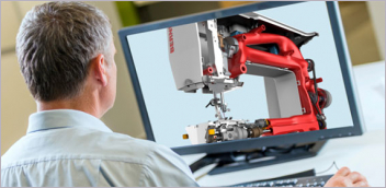
Simulating the general stress distribution on parts and the way composite layers are affected by it go hand in hand. These examples show how the process works in ANSYS simulation software. Images courtesy of ANSYS.

Latest News
October 1, 2019
The transition from metal to composite is one of the most recent significant changes in manufacturing. The former material is isotropic, exhibiting uniform stretching and bending behavior in all directions. By contrast, composites are anisotropic. They stretch, bend and break differently in different directions, based on how the fibers are woven together and how the laminates are bonded. This fundamental difference throws many traditional simulation protocols and practices into chaos.
“Most engineers are educated in the isotropic world, but the behaviors of these advanced materials are exactly the opposite,” says Jeffrey Wollschlager, VP for composite technologies, Altair. He is also an associate professor at the University of Washington, where he teaches a course on composite design.
“It would have been much simpler if engineers have been trained to handle anisotropic behavior from the start. Then, you can simply ask them to disregard certain parts of their formulas to arrive at isotropic. But going from simple to complex, to add a new set of behaviors to isotropic rules, is very difficult,” remarks Wollschlager.
Seth Hindman, senior manager of product strategy at Autodesk, calls composites “something of a black art.” Their creation, manufacturing and application involve so much experimentation and risk that only a few manufacturers have historically been able to reap the benefits of these advanced materials.
In the last 10 years, spurred by the need to understand the black art, CAD and simulation software suppliers began acquiring promising upstarts already making a name for themselves in the emerging discipline (see Sidebar: The Composite Shopping Spree). Today, many of the composite solutions spawned by acquisitions have become robust and mature, ready to assist manufacturers timidly dipping their toes into composites for the first time.
Pursuing the Black Art
Autodesk’s composite-focused software, Autodesk Helius, has roots going back to a Wyoming-based developer called Firehole, acquired by Autodesk in 2013. In the purchase of Pennsylvania-based Magestic Systems, Autodesk gained Magestic’s CNC simulation software for manufacturing composite laminates. The product has since been rebranded Autodesk TruComposites.
Failure modes in forged metal are well understood. Most finite element analysis (FEA) solvers have developed good rules to account for their reaction to stress loads. But not so with composites.
“With composites, you look for delamination, for tearing. In some cases, you need to change the layup strategy to address the residue effects of manufacturing. As you layer them, you get wrinkles and pockets in some areas,” says Hindman. “They can also be porous, so they may take on moisture, which also affects performance.”
The tear begins in one region, then propagates throughout the composite layers that cover the product like an outer skin. Software such as Helius lets you simulate how a small tear or damage may expand over time.
“The fatigue model you need to develop for composites is quite complex, and it’s specific to that composite type,” says Hindman. “After developing it, to make sure the model is valid, you also need to compensate for the different manufacturing processes that might affect the character of the materials.”
For aerospace and automotive manufacturers that have worked with composites, this internal knowledge is precious intellectual property. Their understanding of the failure mechanism and strategies to counteract them is a competitive advantage, so they aren’t likely to publish them for the rest of the industry.
Even if some of these firms are willing to share their knowledge, significant hurdles stand in the way. Since each composite behaves differently depending on its formula and manufacturing process, the fatigue prediction model for one type is not always applicable to other variants of the same type.
Part Quality Linked to Manufacturing
In December 2017, Sweden-based Trelleborg Group acquired Automated Dynamics. Today, the company’s Automated Fiber Placement (AFP) technology has become part of Trelleborg Sealing Solutions. The precision possible with AFP makes the division’s thermoset and thermoplastic sealing components deliver highly consistent performance.
“The ideal situation is where a manufacturer brings us a part that’s been designed for metal, and asks us to work with them to turn it into composite for higher performance,” says Reid Hislop, product manager, Advanced Composites, Trelleborg Sealing Solutions.
One of the composites’ features is its fabric-like character, which can be adapted to different shapes. The materials also have become the preferred choice in many lightweighting projects, where manufacturers seek ways to reduce the weight of an assembly or a product by replacing them with composite parts.
But working with composites is not straightforward. “It gets much more complex, because depending on the direction and orientation of the fibers and the plies, the composite part’s strength is different,” observes Ginger Saunders, project engineer, Trelleborg Sealing Solutions.
The Trelleborg parts made with AFP have a low coefficient of thermal expansion (CTE). This characteristic allows the company to make composite parts that match nearby metal parts in CTE. The company uses Autodesk Helius, among others, to simulate and analyze their production process and material performance.
“Manufacturing variation can certainly affect the quality of parts, but Trelleborg’s automated process can help to minimize this,” explains Saunders. “Our process utilizes automated fiber placement, and when fiber placing thermoplastic materials, there is no need for an autoclave cure [a chamber-like environment to heat the laminates].
“We bond the material in-situ, or on the fly, to consolidate the structure,” Saunders continues. “We qualify the process conditions for all the material that is used in our products to an internal standard, and have consistent repeatability with our equipment.”
Scale-Dependent Answers
In 2015, Altair acquired Multiscale Design Systems, which developed the MDS software for micromechanics design, microstructure optimization and life prediction of complex materials. MDS is now called Altair Multiscale Designer. More recently, Altair acquired Componeering, which developed the ESAComp software for composite simulation.
“Most people use the term composite to refer to laminated composites, like Carbon Fiber Reinforced Polymer (CFRP) or Glass Fiber Reinforced Polymer (GFRP),” says Altair’s Wollschlager. “With modern materials like these, you have to integrate manufacturing simulation and microstructure design.”
In Wollschlager’s view, investigating composite designs at various scales is the key. Being able to obtain the material’s average behavior at the fiber/matrix scale, lamina scale, laminate scale and even the part scale requires multiscale technology.
Multiscale material model development and simulation capabilities of Multiscale Designer are a part of the HyperWorks simulation suite of tools. In addition to software tools, Altair also offers composite engineering services.
Damages Beneath the Skin
In 2013, ANSYS acquired long-time partner Evolutionary Engineering (EVEN), then created ANSYS Switzerland, a wholly owned subsidiary. As a result of the acquisition, ANSYS gained a new product: ANSYS Composite PrepPost, a pre- and post-processing solution for analyzing layered composite materials. The software is integrated with ANSYS Mechanical in ANSYS Workbench, which makes it easier for ANSYS users to adopt.
“If a single material doesn’t give you what you need, you mix two or more materials to get the characteristics and qualities you want,” says Richard Mitchell, principal product marketing manager for Structures, ANSYS.
In the wind energy sector, composite laminates are extensively used in the skin or outer layers of the wind turbine blades. Although some of the blade’s internal structure can be treated and analyzed in classic FEA tools, the composite layers require a different treatment.
“Sometimes after an impact, from the outside the turbine doesn’t look like there’s any damage, but there may be damage inside, so it’s important to be able to simulate and look at what’s happening underneath the top layers,” explains Mitchell. With ANSYS Composite PrepPost, the results for the structure can be looked at globally or viewed in detail down to the layer level.
Mitchell suggests that, for initial design investigation, the general stress distribution can be simulated using ANSYS Discovery Live, a quick analysis tool for designers and non-experts. More detailed investigations may be conducted on the composite layout and orientation using ANSYS Composite PrepPost.
Targeting those who wish to run hundreds of jobs simultaneously, ANSYS plans to launch the ANSYS Distributed Compute Services (DCS), giving users the option to augment their local hardware with additional cloud resources.
The Inside of Your Composite Part
In healthcare, if you need to see beyond the patient’s visible symptoms for a more thorough diagnosis, you run a computed tomography (CT) scan. In manufacturing, if your so-called patient happens to be a composite part, you may turn to Volume Graphics to get something similar—an inside view of the part.
The company was founded in the 1990s by three physicists who wanted to focus on developing software applications to process CT slice-image stacks in 3D. Today, the company’s VGSTUDIO and VGSTUDIO MAX are known as industrial CT scanning software for metrology, defect detection and assessment, material properties analysis and simulations.

The software has an add-on specifically for analyzing fiber-reinforced plastic composites. The fiber composite materials analysis (FCMA) module lets you visualize, analyze and manage local and global fiber orientations and fiber volume fractions. Users are predominantly from the aerospace and automotive sectors, attracted to composites for their lightweighting potential, according to Kamil Szepanski, customer support coordinator, Volume Graphics.
Some FCMA users deploy the module to obtain and verify the fiber orientation in the manufactured part because the data can subsequently be used as input in detailed simulations. “This renders more meaningful results than if it were run on the nominal data,” Szepanski points out.
The insights from using FCMA are key to predicting and preventing common failure modes in composite parts, such as disorientation of fibers, fiber undulation and delamination.
“In composite components, the strength and thermal conductivity are directly influenced by fiber orientation,” explains Szepanski. “In order to achieve an optimal fiber orientation to satisfy the requirements in each particular use case, you can use the results of the FCMA and simulation and stress testing to determine where you need to adjust the production process.”
e-Xstream Composites
Roger Assaker was the CEO of e-Xstream Engineering, headquartered in Luxembourg. After MSC Software acquired e-Xstream in 2012, he kept the same title, but also added a new one: chief material strategist of MSC Software.
“We are 100% focused on multiphase, multiscale advanced material modeling,” explains Assaker. “We have a long history catering to the automotive, where the use of these materials is quite common.”
The all-electric BMW i3 and the hybrid BMW i8 are examples of the automakers’ eagerness to adopt composites. When it comes to making lighter, stronger vehicles, composites are especially attractive to the auto industry.
“With composites, the way you design your materials affects how they perform and behave, so it’s critical to be able to simulate the design process,” remarks Assaker. At the stage where reinforcing materials, such as glass fibers, are added to the base material, called the Matrix, the orientation of the fibers determines the strength of the final product when pulled or stretched from a certain direction.
By the same token, in laminate composites, the stacking and orientation of the sheets affects the strength of the final product. Therefore, the choices made in the design of the material play a crucial role in the overall performance of the final part.
Digimat is MSC Software’s composite-focused product (MSC is now part of Hexagon), and the company offers various tools and modules under that brand. Digimat-RP, for example, is specifically for the design and analysis of reinforced plastic (RP) parts. Digimat-HC is for designing honeycomb (HC) composite structures. Digimat-FE is for examining materials at the microscopic level using representative volume elements.
Multiphysics, Multidiscipline
In 2018, multiphysics simulation software provider COMSOL released its first Composite Materials Module (CMM). “This is not a product we acquired. We wanted a multiphysics solution to this, so we developed this in house,” explains Bjorn Sjodin, VP of Product Management, COMSOL.
Under the COMSOL Multiphysics brand, the company offers various discipline-specific modules, including a module for analyzing laminated composites, commonly CFRP. “But some of our users modify the software to make it more suitable for analyzing unit cells of generic composites,” adds Sjodin.
“This is multiscale modeling, since it lets you analyze the material as microstructures but also as laminates,” says Sjodin. It benefits from COMSOL’s solvers, which can simulate phenomena that must be calculated using more than one type of physics.
“Composite failures can happen at the laminate level due to indirect loads. Because of temperature or unwanted heat, such as a lightning strike producing an electric current, the mixed materials expand in uneven fashion, resulting in tearing, shearing or delamination. It may also fail when wind or water flows across the laminates,” Sjodin points out.
These are examples of multiphysics interactions: fluid and structure, or thermal and structure. To solve the multiphysics phenomena, the workflow may also need to be multidisciplinary. “If you want to understand some advanced delamination phenomena, an FEA expert might not be enough,” Sjodin says. “You may also need a manufacturing expert looking at it, because the resin and the adhesive used are important considerations.”
More Altair Coverage
More Ansys Coverage
More Autodesk Coverage
More COMSOL Coverage
Subscribe to our FREE magazine, FREE email newsletters or both!
Latest News
About the Author
Kenneth Wong is Digital Engineering’s resident blogger and senior editor. Email him at kennethwong@digitaleng.news or share your thoughts on this article at digitaleng.news/facebook.
Follow DE